ENERGY ARCHITECTURE
Solar Energy for Telecom Sites: System Types, Development History and Future Outlook
Solar energy for telecom sites has evolved from a niche option for remote towers into a practical part of grid-connected, bad-grid and off-grid network design. This guide explains where solar fits, how the architecture has changed and what buyers should prepare for next.
Updated July 30, 2026
Engineering and industry guide
Approx. 14-minute read
Solar energy for telecom sites is rarely a panel-only solution. A dependable site normally combines photovoltaic generation with a DC power system, batteries, source controls and, where the risk requires it, grid or generator backup. The design should be judged by network availability, annual fuel and electricity cost, battery life and maintainability – not by installed PV capacity alone.The phrase covers several very different jobs. At an urban macro site, solar may offset a portion of daytime grid consumption. At a rural bad-grid site, it may reduce daily generator hours. At an off-grid tower, it may become the primary energy source while batteries carry the night load and a generator protects against prolonged poor weather. Treating these cases as one product category is where many weak specifications begin.
What Solar Energy for Telecom Sites Actually Includes
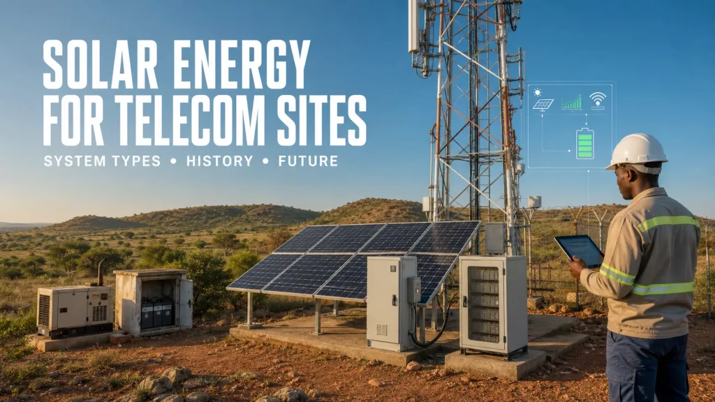 Solar photovoltaic modules generate electricity; they do not store it and they do not guarantee continuity on their own. Telecom equipment also needs regulated power, protection and a stable operating voltage. Most conventional radio and transmission loads use a nominal −48 V DC plant, while cooling, lighting and maintenance outlets may require AC power.
A complete site therefore assigns a distinct job to each energy asset.
Solar photovoltaic modules generate electricity; they do not store it and they do not guarantee continuity on their own. Telecom equipment also needs regulated power, protection and a stable operating voltage. Most conventional radio and transmission loads use a nominal −48 V DC plant, while cooling, lighting and maintenance outlets may require AC power.
A complete site therefore assigns a distinct job to each energy asset.
| Energy asset |
Primary job |
What it cannot do alone |
| Solar PV array |
Produce energy during available daylight |
Cover night load or guarantee output during poor weather |
| Battery storage |
Shift solar energy, bridge outages and support the DC bus |
Create new energy after its usable reserve is exhausted |
| Grid connection |
Supply normal energy where service is available |
Guarantee voltage quality or uninterrupted service |
| Generator |
Provide dispatchable, long-duration contingency power |
Deliver low-cost, low-maintenance energy when run continuously |
| Controller and DC power system |
Regulate voltage, coordinate sources and protect the load |
Correct an undersized array, exhausted battery or empty fuel tank |
Solar modules may be ground-mounted, roof-mounted or installed as a canopy over a shelter or equipment area. Fixed-tilt monocrystalline PV is common because it is simple and has no tracking mechanism to maintain. Bifacial or vertical arrangements can work at selected sites, but only when ground reflectance, shading, wind loading and available area support the choice.
Coupling also matters. A DC-coupled system sends PV energy through solar converters toward the telecom DC bus and battery. This can reduce unnecessary conversion stages for a −48 V load. An AC-coupled system uses an inverter and connects through the site’s AC distribution. It can be convenient for retrofits, but the energy path, islanding behavior and restart sequence must be examined rather than assumed.
Five Practical Solar Telecom System Types
The right architecture follows grid quality and service risk. It should not be selected from a catalogue before the site load and outage pattern are known.
| System type |
Typical energy path |
Best fit |
Main design risk |
| Grid-connected solar assist |
Grid + PV + standby battery |
Reliable-grid urban and suburban sites |
Oversizing PV when export or daytime load is limited |
| Grid solar with active storage |
Grid + PV + cycling battery |
Sites with tariffs, short outages or resilience goals |
Using the backup reserve for savings when an outage follows |
| Bad-grid hybrid |
Weak grid + PV + battery + generator |
Sites with frequent or long utility interruptions |
Poor source logic that wastes fuel or overcycles the battery |
| Off-grid solar hybrid |
PV + battery + generator contingency |
Remote towers without a usable utility connection |
Sizing from annual irradiation instead of the worst operating season |
| Solar-led community energy site |
PV + storage + tower load + controlled local loads |
Locations where the tower can anchor a small energy service |
Mixing telecom resilience with community demand without clear limits |
1. Grid-connected solar assist
This is the simplest use of solar at a telecom site. PV serves the live load when sunlight is available, reducing energy purchased from the utility. The existing battery remains primarily a standby asset. The economics depend on daytime load, electricity price, available area and whether export is allowed or compensated.
It is particularly relevant for sites with a steady base load. Unlike a house, a radio site does not empty during working hours, so it can consume a useful share of midday PV generation directly. Even here, the designer must check reverse-power rules, low-load periods and what the controller does when the battery is already full.
2. Grid solar with active storage
The battery does more than wait for an outage. It may absorb surplus solar, reduce a tariff peak or carry selected load during a short grid interruption. This can improve solar utilisation, but it also creates a reserve-policy problem. The system must decide how much energy may be used commercially and how much must remain available for network continuity.
3. Bad-grid solar-battery-generator hybrid
At a bad-grid site, utility service may exist for only part of the day or may arrive with poor voltage and frequency. The battery cycles much more often than a conventional standby bank. Solar can reduce generator runtime, while the controller decides when to accept the grid, charge the battery or start the generator.
A common failure is to set generator start and stop points without considering minimum efficient loading. The generator starts, charges a nearly full battery at low power, runs inefficiently and stops again. A better control strategy considers state of charge, forecast load, available solar, charging limits and minimum run time together.
4. Off-grid solar hybrid
At an off-grid site, solar and storage carry most operating hours. A generator is still valuable where several days of poor weather, unusual traffic or maintenance can occur. Calling the generator a design failure misses its real role: it is an insurance asset whose annual runtime should be controlled and measured.
Small repeaters, microwave relays and low-power access nodes may operate without a generator where load, climate and service access make sufficient PV and storage practical. A macro site with cooling and multi-sector radio equipment has a different energy profile and should not inherit that assumption.
5. Tower-as-anchor energy service
A telecom tower provides a predictable anchor load and a professional customer. In some remote communities, that can support a larger solar-storage system serving nearby businesses or essential services through separately metered circuits. The telecom reserve, protection and ownership boundaries must remain independent. Community demand should never be able to drain the energy reserved for network service.
How Solar Telecom Power Developed
The history is less a story of panels replacing diesel overnight and more a sequence of improvements in economics, storage, controls and remote operations.
| Period |
Typical architecture |
What changed |
| Before the 2000s |
Grid + lead-acid backup; diesel for remote or long outages |
Reliability depended on conventional power plants and field visits |
| Early to late 2000s |
PV pilots for remote GSM, microwave and repeater sites |
Rural network expansion met high fuel logistics and limited grid reach |
| 2010-2015 |
Solar-diesel hybrids with larger battery banks |
Falling PV cost and tower-company models made fuel reduction more bankable |
| 2015-2020 |
Hybrid controllers, lithium trials and remote energy monitoring |
Operators began managing energy performance across fleets rather than one site at a time |
| 2020-2025 |
PV + LFP storage + multi-source control for 4G and 5G |
Higher loads, denser equipment and better battery telemetry raised the value of integration |
| 2026 onward |
Software-defined source control, predictive maintenance and site energy portfolios |
Attention moves from installed hardware to lifecycle energy, resilience and auditable performance |
In 2009, the GSMA launched a renewable-energy push for mobile networks and estimated that only about 1,500 base stations worldwide were then powered by at least one renewable source. The programme highlighted early wind and solar deployments and the economics of reaching places beyond national grids. That marker is useful because it shows how experimental the sector still was.
During the 2010s, the question shifted from “Can solar power a tower?” to “How much fuel and maintenance can a hybrid system avoid without lowering availability?” Tower companies, energy service companies and remote monitoring platforms helped separate energy performance from radio operations. Solar-diesel hybrids became a commercial operating model rather than a demonstration.
The publication of ITU-T L.1380 on smart energy solutions for telecom sites in 2019 reflected another step. Solar, storage, peak-load shifting and remote control were being treated as coordinated site functions. The controller was no longer a simple changeover relay.
By 2025, the engineering discussion had become more specific. ITU-T L.1211 addressed smart PV control for base-station sites, including module-level control, voltage tracking and PV fault diagnosis. One documented 3.3 kWp installation generated 3,352 kWh from September 2022 through August 2023 and supplied 12% of that site’s energy. It is one site, not a universal yield claim, but it shows the direction: measured production, diagnosed losses and integration with operating data.
A Worked 4 kW Telecom Site Example
Sizing starts with energy, not panel count. Consider a site with a stable average load of 4 kW.
Daily telecom energy:
4 kW × 24 hours = 96 kWh/day
Assume the design-month solar resource is 4.5 peak-sun-hours per day and total system derating is 22% for temperature, dust, conversion, wiring and mismatch.
Indicative PV requirement:
96 kWh ÷ (4.5 h × 0.78) = 27.35 kWp
That calculation suggests roughly 27.4 kWp merely to balance one representative day. It does not yet cover future load, unusual cloud, battery recovery after an outage or seasonal uncertainty. A preliminary design might therefore test a range around 29-32 kWp against hourly simulation and the actual design-month resource.
Now assume the battery must carry the 4 kW load for 12 hours. Use 80% maximum depth of discharge, 92% delivery efficiency and an 85% end-of-life capacity factor.
Indicative battery nameplate energy:
(4 kW × 12 h) ÷ (0.80 × 0.92 × 0.85) = 76.7 kWh
The result is an engineering starting point, not a quotation. Cooling, load peaks, battery power limits, temperature, recharge time, redundancy and generator strategy can move the final number materially. The fuller process is covered in the site’s telecom solar and battery sizing guide.
| Input that changes |
Likely design effect |
| Higher night-time traffic or cooling load |
More battery energy and potentially more PV for next-day recovery |
| Lower design-month solar resource |
Larger PV array, greater storage or more generator runtime |
| High battery temperature |
Faster ageing, thermal-control requirement and earlier replacement allowance |
| Strict no-outage requirement |
Additional redundancy, contingency generation and tested failure response |
| Long travel time to site |
More autonomy, stronger remote diagnostics and a deliberate spares plan |
Operational Lessons That Matter More Than the Brochure
Measure the whole load
Radio power is only part of the site. Cooling, fans, lighting, surveillance, microwave equipment, battery heating, maintenance sockets and conversion loss all consume energy. A temporary logger is usually more useful than a nameplate sum, especially where traffic and ambient temperature vary.
Use the design month, not an annual average
Annual solar yield can make an off-grid design look comfortable while one cloudy season produces repeated generator starts or low-battery alarms. Use at least monthly resource data and preferably hourly simulation. Check horizon shading, nearby trees, tower shadow and future construction.
Make soiling a maintenance variable
Dust, pollen, salt and bird fouling reduce generation unevenly. The problem is not solved by applying one generic loss percentage. Define how output will be compared with expected yield, when cleaning is triggered, how water is supplied and whether technicians can reach the modules safely.
Protect battery life explicitly
The battery specification should state usable energy at end of life, allowable depth of discharge, temperature limits, charge current, communications protocol and warranty throughput. State of charge is an operating estimate; it is not proof that the battery can still deliver the required autonomy.
Keep local control when communications fail
Remote monitoring is essential across dispersed sites, but the power plant must remain safe and functional when the backhaul or cloud service is unavailable. Source priorities, generator controls and battery limits need validated local fallback. Logs should be retained and synchronized later.
Design the enclosure as part of the energy system
Cabinet temperature affects conversion efficiency and battery life. Solar heat gain, dust, salt mist, condensation, insects, cable entries and corrosion all matter. A high IP rating does not demonstrate adequate thermal design. The cabinet, cooling method and installed equipment must be evaluated together.
Useful fleet monitoring should include PV yield, site load, battery charge and discharge, generator energy, fuel level, grid availability, cabinet temperature and conversion loss. The purpose is to explain an energy imbalance, not merely display a dashboard. A practical set of indicators is available in the telecom energy monitoring and KPI guide.
Future Outlook for Solar Energy at Telecom Sites
Solar becomes one controlled input, not a separate subsystem
The next step is tighter coordination among rectifiers, PV converters, batteries, generators and thermal equipment. A controller should understand energy availability and equipment limits at the same time. PV fault diagnosis will matter because a partly failed string can remain electrically connected while silently underperforming for months.
Storage portfolios become more diverse
LFP is widely used where cycling, energy density and remote monitoring are important. Lead-acid remains present in existing standby systems. Sodium-ion, aqueous zinc and other chemistries may find roles where cost, temperature behavior, safety or supply-chain considerations justify them. Buyers should resist chemistry headlines and compare certified systems under the site’s actual duty cycle.
Forecasting moves into local dispatch
Solar forecasts, traffic patterns and outage history can improve charging and generator decisions. The useful version of “AI energy management” is modest: fewer unnecessary starts, better reserve planning and earlier fault detection. The site must still operate safely with fixed fallback settings if forecast data disappears.
Fleet-level energy becomes a procurement unit
Operators will increasingly compare thousands of sites by avoided fuel, renewable contribution, battery health and outage exposure. That favors standardised equipment interfaces and repeatable commissioning. It also exposes underperforming sites that once disappeared inside a regional fuel budget.
Some sites may support grid or community services
Grid-connected batteries could provide tariff response or limited flexibility where regulation permits. Remote tower sites may anchor community microgrids. Neither opportunity should consume the telecom resilience reserve. Electrical protection, metering, commercial ownership and dispatch authority must be separated before secondary services are enabled.
Climate adaptation joins carbon reduction
Higher ambient temperatures, flooding, storms and wildfire-related grid interruption change site requirements. Future solar telecom design will be judged not only by annual carbon reduction but by whether the network remains operable through local climate hazards. Mounting, corrosion protection, drainage, fire separation and spare-parts access become part of the energy case.
Which Architecture Fits Which Site?
| Site condition |
Architecture to evaluate first |
Evidence required before purchase |
| Reliable grid, useful roof or ground area |
Grid-connected PV with standby battery |
Interval load, tariff, export rules and structural survey |
| Reliable grid with demand charges or resilience target |
PV with actively managed storage |
Tariff model, outage risk, reserve policy and battery throughput |
| Grid outages every day |
Bad-grid PV-battery-generator hybrid |
Outage distribution, fuel cost, generator condition and charging limits |
| No usable grid and difficult fuel logistics |
Solar-led off-grid hybrid |
Hourly load, design-month solar, travel time and weather contingency |
| Very low-power repeater or monitoring node |
PV plus battery without routine generator support |
Worst-season autonomy, vandalism risk and physical access |
| Remote community with productive loads |
Tower-anchor microgrid with separated reserves |
Demand study, metering, ownership, protection and service model |
What a Buyer Should Put in the Project Brief
Before requesting prices, provide enough information for suppliers to disagree with an unsafe assumption. At minimum, the brief should include:
- Site coordinates, elevation and available PV area.
- Measured hourly load or representative day and night profiles.
- Grid voltage quality, outage frequency and outage-duration distribution.
- Existing generator rating, age, fuel consumption and minimum loading.
- Required autonomy and the loads that may be shed.
- Monthly solar resource, horizon shading and soiling conditions.
- Ambient temperature, humidity, dust, corrosion, wind and flood exposure.
- Battery end-of-life usable energy and expected cycling duty.
- Required interfaces, alarms, data ownership and local fallback behavior.
- Applicable electrical, structural, battery, fire and grid-connection requirements.
- Factory test, site acceptance, training, spares and response-time expectations.
A credible proposal should return more than a bill of materials. Ask for the load assumptions, solar source, derating factors, monthly energy balance, battery reserve logic, expected generator runtime, single-line diagram, protection concept and operating sequence. That evidence makes different suppliers comparable.
Practical rule: design solar energy for telecom sites around the worst credible operating period and the required service availability. Then use normal-year production to estimate savings. Reversing that order usually produces an attractive payback model and a fragile site.
Start with one difficult site, then design the fleet standard.
Choose a representative location with measured load, real outage history and known maintenance cost. Model several architectures, commission the selected system and compare predicted performance with at least one full operating season before applying the design widely.
Which constraint is defining your project today: grid quality, fuel logistics, battery autonomy, installation area or remote maintenance?