Why does condenser air recirculation affect telecom cooling?
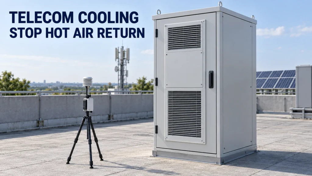 Condenser air recirculation occurs when heated discharge air returns to the condenser intake. The refrigeration system then rejects heat into air warmer than the undisturbed surroundings, which can reduce available cooling and increase compressor demand; the extent depends on the unit’s operating characteristics.
The 2024 ASHRAE Handbook chapter on condensers identifies recirculated discharge air and poor siting as causes of elevated entering-air temperature. Its discussion also connects elevated condensing temperature with capacity and power penalties. Those mechanisms explain why a clear external air path matters; they do not supply a universal clearance or a cabinet-specific derating curve.
The condenser releases heat removed from the cabinet together with heat associated with refrigeration power input. Its discharge therefore needs a route away from its intake. A wall may redirect that discharge, while a tight canopy can create a warm pocket. Another unit may supply the warm air even when the affected cabinet’s own outlet is unobstructed.
Identify the external inlet and outlet from the exact model’s drawing. A visible fan grille does not reliably reveal flow direction across different products. Keep the outdoor condenser circuit separate from the cabinet’s internal cooled-air circuit when marking the plan; a blocked internal return path is a different investigation.
If the architecture itself is still undecided, start with the telecom cabinet cooling selection guide. This article assumes refrigeration equipment has already been selected and concerns its installed external air path.
Trace the installed air path before measuring
Mark the intake and discharge openings on the as-built drawing, then trace where the discharge can go before it mixes with the wider outdoor air. Identify any route back to the same unit or into another unit. Record the project’s design climate separately from the local conditions measured during the visit. Document whether the proposed location is a coastal rooftop, an inland compound or a screened service area. Do not assign the same local airflow to all three. Photograph the surrounding structures from intake height and above the cabinet, including temporary items such as stored materials. Record the relative heights of the outlet, parapet and canopy; a plan view alone can miss a trapped vertical discharge. A measured breeze during a morning visit does not prove that discharge will clear the roof during the critical operating period. Include observed wind direction and changes in the test record. For design review, ask how the layout behaves with little wind and with winds that push neighbouring exhaust toward the cabinet. An orientation that works during one wind condition may fail during another. Use the as-built roof arrangement. A later solar-array extension, architectural screen or second operator’s equipment can change an air path that was open at commissioning. Mark planned additions as well as existing obstructions so that cooling access survives the next construction package.How can a team check whether hot exhaust reaches the condenser inlet?
Compare simultaneous, radiation-shielded air-temperature measurements at the condenser intake and at a nearby reference point outside equipment exhaust. Relate the difference to cooling operation, load and wind. A persistent intake rise associated with a discharge path is evidence to investigate, not a stand-alone proof of recirculation.Place sensors to answer a defined question
Measure condenser inlet temperature in the entering airstream without touching hot metal or obstructing the grille. Use multiple intake positions if the opening is broad or the suspected plume reaches only one edge. Place the reference sensor away from sun-heated surfaces and exhaust from other equipment, at a documented height appropriate to the comparison. Before installation, compare the two air sensors side by side under the same stable, shaded condition and document their difference. This checks relative agreement; it does not replace calibration. Keep the sensor identities and locations unchanged for the retest, and check agreement again if the apparent improvement is small. A warmer intake probe and a cooler reference probe can create a misleading difference even when both readings look plausible. A handheld infrared reading of a painted panel is a surface temperature, not the temperature of moving air. Likewise, a sensor in direct sunshine can report radiation effects that resemble an air-temperature rise. Check sensor accuracy, response time and shielding before interpreting small differences.Log operation alongside temperature
Synchronize the temperature log with cabinet load, compressor and fan state, relevant controller alarms, and neighbouring units’ operation where that information is available. Keep cabinet doors in their normal operating position. An open door changes the test boundary and should not become an improvised cooling remedy. Choose the sampling interval and observation duration to capture the unit’s cycling behaviour. Record when conditions stabilize, when loads change and when a gust alters the readings. Compare like operating periods; a cooler afternoon after a relocation cannot, by itself, establish that the relocation solved the problem.Use a safe comparison to test the explanation
Where the site owner and equipment supplier permit it, compare the baseline with an approved removal of a nonessential obstruction or another reviewed layout change. Keep critical telecom power and cooling protection active. Do not reach through guards, attach loose materials to fan openings or bypass alarms to extend the trial. Relocation, electrical work and refrigerant work require the responsible qualified team.Read the pattern before choosing the repair
A high cabinet temperature can have several causes at once. The following observations help decide which evidence to request next; none replaces the equipment service procedure.| Observed pattern | Working explanation | Next check |
|---|---|---|
| Intake rises relative to reference when a neighbouring unit runs | Cross-unit exhaust ingestion is plausible | Map both units’ discharge directions and compare synchronized operating periods |
| Intake rise changes with wind direction beside a tall screen | The screen may redirect the warm plume | Compare wind records and inlet positions; assess an approved alternative layout |
| Intake tracks reference, but cooling remains poor | External recirculation is not established | Check coil condition, fan operation, internal airflow and load against the service information |
| One sensor reads high even while cooling is off | Radiation, nearby heat or placement may bias the reading | Review shielding and mounting before blaming the refrigeration circuit |
| Both intake and reference rise together | Ambient conditions or the reference location may explain the change | Check a second suitable reference and the model’s performance envelope |
How much space should a telecom condenser have around it?
Use the exact cooling unit’s installation requirements for inlet, discharge and service access, then check whether the surrounding layout returns exhaust to the intake. A single generic gap is insufficient for different outlet directions, wall heights and neighbouring heat sources. Rittal’s technical system catalogue, cooling-unit siting guidance on page 32 illustrates external-circuit spacing and keeping an outlet clear for the products it covers. This is manufacturer-specific guidance, not a universal requirement or a specification for Huijue equipment. Obtain the released manual for the actual unit before accepting the layout. Mark cooling airflow clearance separately from the space needed to open doors, remove a filter or replace a fan. A maintenance aisle can still lie in a hot exhaust stream. Conversely, a large open area on the wrong side of a cabinet may provide no relief to a blocked outlet. Moving a cabinet or changing the orientation of a proposed installation can improve separation, but must be checked against cable routes, structural support, access, drainage and the manufacturer’s permitted mounting position. In a row of cabinets, review the full row under simultaneous operation rather than approving each cabinet in isolation. A sunshade can reduce solar exposure while making external airflow worse if it encloses the discharge. Request a section drawing showing how hot air leaves below or beyond the shade. Any baffle, duct or additional fan needs equipment-supplier approval for airflow resistance, weather exposure and maintenance; do not assume an improvised exhaust extension is harmless.A fictional before-and-after record
Suppose a survey records reference air at 42°C and intake air at 49°C during a stable operating interval. The observed intake uplift is 7 K. After an approved obstruction change, a comparable interval records 43°C at the reference and 46°C at the intake, giving a 3 K uplift.
Intake uplift used in this comparison
Intake uplift = condenser intake air temperature − reference air temperature
Baseline: 49°C − 42°C = 7 K
Retest: 46°C − 43°C = 3 K
Change in uplift: 7 K − 3 K = 4 K
The uplift has fallen by 4 K in this invented example. Compare that change with measurement uncertainty, load, compressor state and wind records before crediting the intervention. The absolute intake fell only 3°C because the reference condition also changed; comparing only the two intake readings hides that distinction.
These temperatures are illustrative, not design weather, field results or acceptance limits. Neither a 3 K uplift nor any other universal temperature difference proves compliance. Assess the measured intake against the actual unit’s performance data and the cabinet’s agreed component-temperature limits. A lower intake temperature does not establish a particular energy saving or restored cooling capacity.
The difference is a screening metric, not a measurement of the percentage of exhaust being recirculated. Without airflow and mixing information, temperature subtraction cannot establish that fraction. Nor should a single average hide one hot section of a large coil face; retain the individual intake readings when deciding whether the correction is adequate.
If the intake improves but the cabinet still overheats, retain the successful airflow correction and reopen the remaining causes. Use the telecom enclosure heat-load calculation for the load assessment rather than expanding this survey into an unsupported refrigeration sizing exercise.
Close the fault with a repeatable acceptance record
A useful closure decision needs three separate findings: the installed geometry meets the actual unit’s requirements, the evidence supports removal of the identified return path, and the cabinet maintains its agreed component conditions during the specified operating cases. A cooler intake alone satisfies none of those findings completely. Before the retest, agree the permitted load, required operating cases, measurement points and temperature limits. Record any conditions that could not be observed. A mild-weather demonstration supports only the tested boundary; it does not establish performance at the project’s hottest specified condition.- Keep dated plan and section drawings showing the accepted intake and discharge paths, clearances and surrounding equipment.
- Attach sensor identifiers, accuracy information, locations and synchronized baseline and retest logs.
- Identify the cooling model, manual revision, controller settings and relevant fan or compressor states.
- Document what changed, who approved it, the remaining exceptions and who owns each follow-up.
- Require another airflow review when screens, PV arrays, cabinets or neighbouring cooling equipment are added.