What is an integrated telecom energy cabinet?
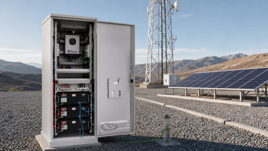 An outdoor equipment cabinet protects hardware from weather and unauthorized access. A telecom power cabinet adds conversion and distribution. An integrated telecom energy cabinet goes further: its mechanical, electrical, thermal and digital functions are designed around one stated site-energy architecture.
The distinction is practical rather than semantic. If a supplier provides only a metal enclosure, the EPC or operator must still coordinate rectifiers, solar controllers, batteries, protection, cooling, cable entries, monitoring and field wiring. If the supply boundary is an integrated cabinet, those interfaces can be engineered, assembled and functionally checked together before shipment. The purchase specification must say which interpretation applies.
An outdoor equipment cabinet protects hardware from weather and unauthorized access. A telecom power cabinet adds conversion and distribution. An integrated telecom energy cabinet goes further: its mechanical, electrical, thermal and digital functions are designed around one stated site-energy architecture.
The distinction is practical rather than semantic. If a supplier provides only a metal enclosure, the EPC or operator must still coordinate rectifiers, solar controllers, batteries, protection, cooling, cable entries, monitoring and field wiring. If the supply boundary is an integrated cabinet, those interfaces can be engineered, assembled and functionally checked together before shipment. The purchase specification must say which interpretation applies.
A clear cabinet boundary should state: which energy inputs enter it, which loads leave it, what is installed inside, what remains external, which alarms are exposed and who is responsible for every connection.
Not every project should force all functions into one enclosure. A separate battery compartment, external solar combiner, independent telecom equipment cabinet or multi-cabinet arrangement may improve safety, expansion, weight distribution or maintenance. Integration is valuable when it removes interfaces without creating an enclosure that is difficult to cool, transport or service.
The seven functions inside the cabinet boundary
Cabinet layouts vary, but a complete design review normally follows the power path from source to load and then checks the systems that keep that path operable.| Function | Typical equipment or provision | Question to settle before selection |
|---|---|---|
| Energy input | Grid, generator, PV, optional wind, isolators and surge protection | Which sources exist, how stable are they and where is the protection boundary? |
| Conversion and control | Rectifier, MPPT controller, inverter, DC/DC converter and source controller | What voltage windows, peak currents and source-priority rules must be supported? |
| Storage | Battery modules, BMS, disconnects, overcurrent protection and battery cabling | Is storage inside the cabinet, in a segregated compartment or in a separate enclosure? |
| Distribution | Busbars, breakers or fuses, critical branches, auxiliary supply and metering | Which loads are critical, shed-able or reserved for future expansion? |
| Thermal management | Passive heat path, filtered fans, heat exchanger, air conditioner or heater | Can every installed component remain within its approved limits at the design climate and load? |
| Monitoring and alarms | Controller, energy meters, temperature and humidity sensing, door, smoke and water alarms | What must be visible locally and at the NOC, through which protocol and with what fallback? |
| Mechanical and protective system | Frame, panels, rack rails, locks, gaskets, cable glands, grounding and mounting hardware | How will the populated cabinet be delivered, installed, sealed, grounded and maintained? |
Do not turn a common voltage into a universal rule
Nominal negative 48 V DC remains common in telecom networks, but it is not the only interface. Current ITU-T L.1210 guidance discusses AC, conventional telecom DC, higher-voltage DC, low-voltage DC and power-over-Ethernet applications. The cabinet must be designed around the approved operating window of the radio, transport, cooling and auxiliary equipment, including polarity, transient behavior and cable voltage drop. A public Huijue satellite-communication cabinet provides one useful example of a model-specific architecture: PV modules, MPPT control, lithium storage, thermal management and distribution are packaged for an off-grid application. Its published outputs and ratings belong to that product, not to every Huijue telecom cabinet configuration.Choose the format after defining the job
Huijue’s cabinet engineering material covers compact wall or pole-mounted enclosures, floor-standing integrated cabinets and larger assembled frame-and-panel structures. Those are useful format families, not a ladder in which bigger automatically means better.Wall or pole-mounted cabinet
This format suits a compact power or network node where ground area is limited and installed weight remains compatible with the supporting structure. Front-only maintenance is often desirable. The design review should focus on lifting, mounting loads, cable bend radius, door clearance, solar exposure and whether technicians can safely replace the heaviest component at working height.Floor-standing integrated cabinet
A floor-standing cabinet provides more room for rack equipment, power conversion, distribution and batteries. It can support front-only or front-and-rear service, depending on the site. Foundation, plinth height, drainage, anchoring, total populated weight and transport route become part of the product specification rather than field details to solve later.Assembled or modular structure
A knock-down or panelized structure can solve a genuine logistics problem when a fully assembled cabinet cannot pass through a narrow access route or be lifted into position. It also adds work at site. The project should define assembly instructions, fastener control, gasket continuity, grounding continuity and the inspection needed to restore the intended enclosure performance after assembly. One site can also use two coordinated cabinets: for example, power and telecom equipment in one enclosure with batteries in another. This can reduce thermal interaction and simplify battery replacement, although it adds inter-cabinet cabling, protection and installation scope. Compare arrangements at the system level, not by enclosure price alone.Thermal design is an energy-system decision
A cabinet does not create a cool environment by being weatherproof. Solar heating, ambient temperature and losses from rectifiers, controllers, batteries and cables all contribute to its internal temperature. Cooling equipment then becomes another site load and, in an off-grid system, can change the PV and battery requirement. The first thermal calculation needs at least:- maximum and minimum ambient temperature, solar exposure, altitude and humidity;
- normal and worst-case heat dissipation of each installed device;
- component operating limits and any temperature derating;
- required enclosure protection, dust or salt exposure and condensation risk;
- cooling power available during grid, generator or controller failure;
- filter inspection, cleaning and replacement intervals that the operator can actually maintain.
What an IP rating does and does not tell you
IEC 60529 classifies degrees of protection provided by an enclosure. It does not, by itself, confirm corrosion resistance, thermal performance, impact resistance, UV durability, fire behavior or suitability for a particular telecom site. The offered IP classification should also match the cabinet as supplied: doors, glands, vents, cooling equipment and field cable entries included. A high enclosure rating on an empty shell is poor evidence if technicians must create unsealed openings during installation. Destination requirements and evidence should be reviewed through the site’s telecom energy standards and compliance guide.Internal layout should follow failure and service boundaries
Rack units are only one part of usable space. A serviceable layout needs clearance for terminals, cable bends, breaker operation, airflow, battery removal and future modules. It should also keep incompatible tasks apart. During a layout review, trace these boundaries:- Energy boundary: separate incoming sources, conversion, storage and outgoing load branches clearly enough to isolate and test them.
- Thermal boundary: prevent hot exhaust or solar-heated panels from raising battery or controller temperature beyond approved limits.
- Maintenance boundary: allow a technician to replace a fan, filter, rectifier, controller or battery module without dismantling unrelated equipment.
- Safety boundary: provide barriers, covers, labels, earthing and access control appropriate to the installed voltages and stored energy.
- Growth boundary: reserve physical space, current capacity and protected ways for the agreed expansion case, rather than leaving an unqualified empty bay.
Monitoring must support an operator, not just a dashboard
A remote cabinet should expose enough information to distinguish a source problem, battery problem, thermal problem and load problem before a truck is dispatched. A single “cabinet alarm” does not do that. ITU-T L.1395 provides a useful framework by separating performance, configuration, fault and log management for telecom power, cooling and building-environment systems. For a cabinet RFQ, translate that framework into a point list.| Information group | Examples to define | Operational use |
|---|---|---|
| Source and conversion | Input state, voltage, current, power, energy, controller mode and protection alarms | Identify source loss, poor input quality, curtailment or converter derating |
| Battery | State of charge, state of health, voltage, current, temperature, limits and alarms | Assess reserve, charging recovery and degradation risk |
| Load and distribution | Total and branch current, breaker state, load-shed state and low-voltage events | Separate a power shortage from a branch or load fault |
| Cabinet environment | Temperature, humidity, cooling state, filter alarm, door, smoke and water detection | Plan maintenance and investigate environmental threats |
| Records and access | Time synchronization, event history, settings, user roles, local fallback and protocol | Support root-cause analysis and controlled remote operation |
A practical cabinet selection workflow
Do not size from the cabinet outward. Start with the operating requirement and let it determine the enclosure.- Freeze the load boundary. Record typical, peak and time-varying demand for radio, transmission, cooling and auxiliaries. Identify AC and DC interfaces and the permissible operating voltage of each load.
- Define source behavior. Document grid quality and outages, generator capability and fuel constraints, solar resource, source priority and credible source failures.
- Set the continuity requirement. State required autonomy, reserve policy, recovery time, critical branches and whether non-critical loads may be shed.
- Select and size the power path. Establish conversion capacity, storage, distribution, protection and cable current from the load and recovery case. Use the detailed solar and battery sizing method where PV and storage are involved.
- Complete the environmental design. Calculate internal heat, choose the thermal method and define enclosure, material, coating, drainage, condensation and corrosion requirements.
- Lay out service and safety zones. Check access, lifting, isolation, battery handling, cable entry, grounding, labeling and expansion.
- Define monitoring and control. Approve the operating-state matrix, source transitions, setpoints, alarms, data protocol, cybersecurity boundary and local fallback.
- Write the acceptance plan. Connect every requirement to a drawing, calculation, report, factory test or site test before production starts.
What to put in a telecom energy cabinet RFQ
A useful request for quotation gives the engineering team enough information to propose a boundary and identify missing data. “Outdoor solar cabinet, 48 V, IP65” is not enough.Site and operating data
- country, site coordinates, altitude, access route and destination requirements;
- hourly or interval load profile where available, plus peak and startup demand;
- load list with criticality, input voltage window, connector and grounding information;
- grid outage and power-quality records, generator data and solar-resource basis;
- required autonomy, reserve, recovery time, availability target and future load case;
- ambient temperature, solar exposure, humidity, dust, salt, flooding, wind and other local hazards.
Cabinet and interface data
- installation method, maximum footprint and height, access clearance and foundation constraints;
- maximum shipping module, lifting method, door or passage limits and site assembly restrictions;
- equipment to be factory-installed, free-issued by the customer or installed at site;
- battery location, replacement method and required segregation;
- cable quantity, size, entry direction, gland responsibility and bend-radius allowance;
- grounding, lightning and surge-protection interface with the wider site;
- required measurements, alarms, communication protocols and NOC integration;
- applicable standards, exact evidence required and FAT/SAT witness points.
Factory acceptance should test behavior, not appearance alone
A clean wiring photo is useful, but it does not prove source transitions, battery reserve, alarms or thermal control. The FAT plan should be derived from the approved operating-state matrix and conducted within safe, documented test limits. Typical checks include:- model, option, BOM, drawings and nameplate consistency;
- mechanical inspection, access, locks, seals, cable-entry provisions and protective bonding;
- wiring, terminal identification, polarity, torque records and protection-device settings;
- normal energization and approved transitions among available sources;
- battery charge, discharge, low-reserve response and recovery logic;
- critical and non-critical branch operation, including authorized load shedding;
- cooling, heating and emergency ventilation behavior where included;
- sensor, alarm, event history, time stamp, local display and remote communication checks;
- loss-of-communication and controller fallback behavior;
- closure of deviations and issue of as-built single-line, wiring, terminal, settings and alarm documents.
Common selection mistakes
- Choosing by rack units first: leaves no defensible thermal, cable or battery service allowance.
- Assuming the bus voltage: can create incompatible loads, unnecessary conversion or excessive cable loss.
- Treating cooling as an accessory: ignores its energy consumption, failure response and maintenance burden.
- Specifying an IP number without the final configuration: separates the claim from glands, vents, doors and cooling equipment that determine the installed enclosure.
- Putting every function in one compartment: may make thermal management, isolation or component replacement harder.
- Leaving monitoring until commissioning: often reveals missing sensors, protocols or alarm ownership too late.
- Comparing quotations with different boundaries: makes a shell, a partly populated cabinet and a factory-tested system appear equivalent.
Frequently asked questions
What is the difference between a telecom cabinet and a telecom energy cabinet?
A telecom cabinet may only house communications equipment. A telecom energy cabinet has a defined power-system role and normally includes some combination of conversion, storage interface, protected distribution, thermal management and monitoring. The purchase specification should state the supplied functions rather than relying on the name.Can batteries and telecom equipment share one cabinet?
They can in a properly engineered configuration, but co-location is not automatically the best answer. Battery technology, heat, service access, module weight, electrical isolation, fire strategy and local rules determine whether one compartment, segregated compartments or separate cabinets are appropriate.Is IP65 always better than IP55 for an outdoor telecom cabinet?
No. The required ingress protection depends on exposure and the applicable specification. A more sealed enclosure may also require a different thermal solution. Confirm the rating on the final configuration and review dust, water, corrosion, impact, condensation and maintenance as separate requirements.Does every telecom energy cabinet use a -48 V DC system?
No. Nominal negative 48 V DC is common, but telecom sites can include AC, other DC interfaces and power-over-Ethernet. Use the load equipment’s approved voltage window and the project’s distribution architecture.What information is needed for a preliminary cabinet design?
At minimum: site location and climate, load profile and voltage interfaces, available sources, outage behavior, autonomy and recovery target, installation and access limits, battery scope, monitoring requirements and destination standards. Missing data should be listed as assumptions, not silently replaced by a standard cabinet.Engineering references
- ITU-T L.1210: Sustainable power-feeding solutions for IMT-2020 networks
- ITU-T L.1395: Monitoring and control interface for telecom power, cooling and building environment systems
- IEC 60529: Degrees of protection provided by enclosures (IP Code)
- Huawei Digital Power: One Site One Cabinet industry reference
- Huijue: Satellite communication energy cabinet example