A cabinet label can conceal a scope gap. One supplier’s telecom power cabinet may include rectifiers, solar control, batteries and protected load distribution. Another may supply only conversion and breakers. An equipment cabinet can mean a dedicated 19-inch ICT bay, or it can be used loosely for any outdoor electronic enclosure.
The distinction therefore has to be drawn from functions and interfaces, not from the name on a quotation. A useful split puts source conversion and fault-energy control on one side, service-producing network equipment on the other, and assigns every cable, alarm and environmental dependency between them.
The names describe roles, not guaranteed bills of material
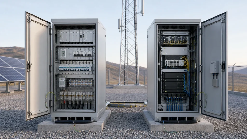
A telecom power cabinet is normally organized around the energy path. Its boundary can begin at grid, generator or renewable inputs and end at protected AC or DC load terminals. Conversion equipment, source isolation, surge protection, distribution, battery connections, metering and a site controller may all fall inside that boundary. Which functions are actually included remains project-specific.
A telecom equipment cabinet is normally organized around ICT payload. Depending on the network architecture, it may contain baseband or distributed units, transmission equipment, routers or switches, optical termination, timing equipment, edge-compute hardware and their local auxiliaries. It still needs power distribution and environmental control, but those functions may be supplied locally or received from the power cabinet.
The terminology is not universal. ITU-T K.35 uses the broader concept of an electronic equipment cabinet at a remote site and notes that telecommunications equipment, power-supply equipment, batteries, temperature-control equipment, optical transmission equipment and ancillary equipment can be installed in outdoor cabinets. That broad scope explains why the same physical product may be sold as a power cabinet, equipment cabinet or integrated cabinet.
For the system-level view, use the integrated telecom energy cabinet guide. This comparison owns the narrower decision: where power functions stop, where ICT functions begin, and whether they should share an enclosure.
What normally belongs in each enclosure
The table is a design starting point, not a fixed product specification. A project decision means the location depends on the battery technology, heat balance, maintenance method, site ownership and applicable requirements.
| Function or component | Power cabinet | Equipment cabinet | Boundary question |
|---|---|---|---|
| Incoming grid or generator isolation | Normally located here | Normally not included | Where is the first safe isolation point for site power? |
| PV input, combiner interface and MPPT control | Normally located here for a solar site | Normally not included | Is PV protection inside the cabinet or at the array? |
| Rectifiers, DC/DC converters or inverter | Normally located here | Only when integral to a specific ICT load | Who owns conversion capacity, redundancy and settings? |
| Battery strings or modules | Common, but not automatic | Possible only with an engineered compartment | Do weight, heat, service and hazard controls support co-location? |
| Main AC/DC load distribution | Normally located here | Receives feeders; may add local branch protection | Which device protects the cable and which isolates the load? |
| Baseband, transmission and routing equipment | Only if rack space and environment are designed for it | Normally located here | What are the approved voltage and environmental limits of each load? |
| Optical distribution and patching | Usually avoided unless a coordinated zone is provided | Normally located here | Can fiber bend radius and access be maintained away from power work? |
| Cooling, heating and ventilation | Project decision | Project decision | Are the two heat loads and environmental windows compatible? |
| Environmental and security sensors | Usually required for its own space | Usually required for its own space | Which controller reports door, temperature, smoke and water alarms? |
| Site monitoring gateway | Often located here | Can be located here or in a separate controller | Who owns protocol conversion, time stamps and NOC delivery? |
Battery placement is a clear example of why the table cannot be turned into a universal rule. Appendix I of ITU-T L.1221 illustrates batteries both inside and outside a telecom power cabinet. Those figures are implementation examples rather than a mandate. The final arrangement still has to account for technology, temperature, current, cable length, lifting, service access and the project’s safety strategy.
Why the split changes site behavior
Fault work can be separated from network work
Power technicians need access to source isolators, surge devices, rectifier shelves, battery disconnects and distribution terminals. Network technicians need access to optical patching, transmission ports, radio interfaces and replaceable ICT modules. Separate service zones can prevent one task from exposing the other team to unrelated electrical hazards or interrupting airflow and cabling around live network equipment.
Separation is only useful when isolation is real. If technicians must open the equipment cabinet to disconnect the power cabinet, or route an unprotected feeder through both spaces, the drawing has created two labels rather than two controlled work areas.
Heat sources and acceptable temperatures may differ
Rectifiers, solar controllers, inverters, batteries and cables create one heat profile; radio, baseband and transport equipment create another. Battery charging limits can be more restrictive than the operating range of nearby electronics. Conversely, ICT equipment with high processing load may require more cooling than a lightly loaded conversion bay.
A shared cooling system can reduce equipment count, but it also couples the spaces: a cooling fault affects both the energy path and the service load. Separate thermal zones allow different setpoints and maintenance schedules, while adding fans, heat exchangers, air conditioners, controls and energy consumption. The correct choice follows a cabinet heat balance and credible failure cases.
Expansion ownership becomes visible
Radio capacity can grow while the existing cabinet still has rack units available but no feeder capacity, cooling reserve or cable-entry space. Power capacity can also be upgraded while the equipment bay remains unchanged. Separate cabinet schedules make these constraints easier to track, provided the interface schedule records spare breaker ways, permitted load growth, connector type, voltage window and available thermal margin.
Four workable enclosure arrangements
| Arrangement | Where it fits | Main advantage | Main design risk |
|---|---|---|---|
| Separate power and equipment cabinets | Sites with different owners, maintenance teams, heat loads or expansion cycles | Clear isolation and service responsibility | More footprint, inter-cabinet cabling and field interfaces |
| One enclosure with segregated compartments | Compact sites that still require electrical, battery or thermal separation | Factory-integrated interfaces with controlled service zones | A common shell, plinth or cooling failure may still affect both compartments |
| Shared mixed-equipment bay | Small loads where compatibility and maintenance access are demonstrated | Lowest enclosure count and short internal connections | Heat, cable congestion and one maintenance action can affect the entire site |
| Power cabinet with outdoor-rated ICT at point of use | Distributed radio or repeater sites with little central indoor ICT equipment | Compact ground installation and reduced equipment-cabinet volume | Each field device needs a defined power, surge, grounding, fiber and environmental interface |
Commercial products demonstrate that these boundaries are configurable. Eltek’s published Type 4 outdoor cabinet datasheet describes one bay that can support DC power, battery backup, telecom equipment or a combination. Delta’s OutD cabinet reference likewise presents several sizes, thermal options and configurations that may build the base station inside the cabinet. These are vendor-specific examples, not evidence that mixed occupancy suits every site.
Huijue’s cabinet platform can be configured around compact wall or pole installations, floor-standing enclosures and larger modular structures. Available power, battery, ICT and thermal functions should be confirmed against the exact project configuration; cabinet family names alone do not establish the supplied boundary.
Design the boundary through five interfaces
1. Electrical supply interface
List every load with normal demand, peak demand, input type, approved voltage window, polarity where relevant, connector, protective device and criticality. Then define the delivery point: cabinet busbar, breaker output, terminal block or equipment connector. The power cabinet rating must include simultaneous load, conversion losses, charging demand and the agreed growth case.
Do not assume that every load shares one nominal DC interface. The site may contain AC auxiliaries, conventional telecom DC, DC/DC-fed devices, inverter loads or power-over-Ethernet equipment. Cable voltage drop and protection coordination belong to the interface, not to either cabinet in isolation.
2. Thermal and airflow interface
Provide a heat-dissipation schedule for both cabinet populations at normal and credible worst-case operation. Record air inlet requirements, exhaust direction, recirculation risk, component derating and the environmental range that each item can accept. If compartments share cooling, specify airflow paths and response when a door, fan, filter, heat exchanger or air conditioner is unavailable.
3. Battery interface
Define battery location, chemistry, module mass, disconnect and overcurrent protection, cable route, charging limits, monitoring, replacement method and isolation procedure. If storage shares a shell with ICT equipment, confirm thermal interaction, physical access, electrical separation and the applicable project safety requirements. If storage is external, assign the inter-cabinet cable, protection at each end and voltage-drop limit.
4. Bonding, grounding and surge interface
The enclosure split must not produce separate, uncoordinated earthing schemes. Show the site earth termination, protective bonding of each cabinet, cable shields, surge-protective-device connections and bonding across doors, panels, plinths and cable trays. ITU-T K.35 is a useful primary reference for bonding and earthing at remote electronic sites; final design remains subject to the operator specification and destination requirements.
5. Monitoring and responsibility interface
Power, battery, cooling and ICT alarms often originate in different controllers. Define a point list that identifies signal source, unit, normal state, threshold, delay, severity, time stamp, protocol and owner. ITU-T L.1395 treats power, cooling, environment and ICT monitoring as functional equipment subsets connected through a management architecture. That approach is more reliable than assigning all alarms to whichever cabinet happens to contain the gateway.
Review an existing site before adding another cabinet
An expansion project often starts with an installed equipment cabinet and a request for more power. Before adding a new telecom power cabinet, record the actual boundary rather than relying on the original drawing.
- Survey the live loads. Measure demand over representative traffic and temperature conditions. Identify startup, transmit and cooling peaks.
- Trace every feeder. Record source, protective device, cable, termination, voltage at the load and any undocumented local converters.
- Inspect the service path. Check whether a new cabinet can be isolated, lifted, opened and maintained without blocking the equipment cabinet or tower access.
- Rebuild the heat balance. Include both the proposed power losses and any new ICT heat, plus solar loading and the consumption of added cooling.
- Check spare physical interfaces. Count usable cable entries, breaker ways, terminals, rack clearances and grounding points rather than empty-looking space.
- Define the transition sequence. State how the live site moves to the new feeder, what temporary supply is required and how rollback will work if commissioning fails.
The wider telecom site energy engineering guide covers load survey, source architecture, sizing, commissioning and lifecycle operation beyond the cabinet boundary.
Require documents that make the split testable
A quotation should show more than two enclosure outlines. Ask each supplier to issue a coordinated document set with the same revision and interface identifiers.
- Scope and responsibility matrix: equipment supplied, factory-installed, free-issued or installed at site, including every inter-cabinet cable and gland.
- Single-line diagram: energy sources, isolation, conversion, storage, distribution, protection, load feeders and grounding references.
- General arrangement: rack units, compartments, battery trays, service clearances, airflow, lifting points, foundation and populated mass.
- Heat-load and cooling schedule: losses by device, design ambient, solar assumption, derating, cooling capacity, auxiliary demand and failure response.
- Cable and terminal schedule: origin, destination, conductor, protection, gland, connector, polarity, shield and installer responsibility.
- Monitoring point list: measurements, states, alarms, thresholds, protocols, time stamps, remote actions and fallback behavior.
- Factory and site acceptance plan: inspections and functional tests that prove the interface as well as each cabinet in isolation.
During FAT, simulate loss and restoration of the agreed sources, verify protected outputs, confirm alarm ownership and check that work in one service zone does not require uncontrolled access to the other. During SAT, verify cable protection, polarity, voltage at the load, grounding continuity, communications and the transition from temporary to permanent supply.
Engineering references
- ITU-T K.35: Bonding configurations and earthing at remote electronic sites
- ITU-T L.1221: Innovative energy storage technology for stationary use – battery
- ITU-T L.1395: Monitoring and control interface for power, cooling and building environment systems
- IEC 60529: Degrees of protection provided by enclosures
Standards, operator requirements and supplier data must be checked for their current edition and exact project scope. Reference to a standard does not claim certification of a Huijue product or integrated site.
Turn the cabinet split into an interface schedule
Send the load list, source diagram, cabinet locations, environmental data and ownership boundary. Huijue can propose a separate, compartmented or integrated arrangement with the assumptions and field interfaces identified for review.
Request a cabinet boundary review