Which standards govern telecom tower grounding and bonding?
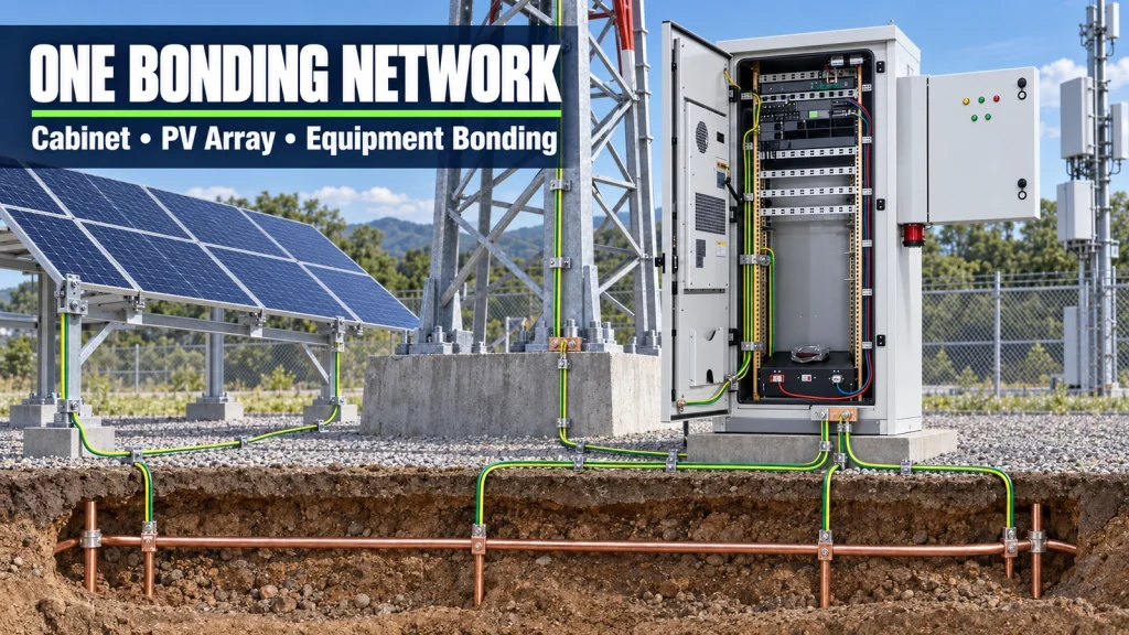 Telecom tower grounding is governed by a project-specific stack rather than one universal rule: destination electrical law, the authority having jurisdiction, operator requirements, the approved lightning-risk assessment, the earthing arrangement of the incoming supply and the standards invoked by contract. International standards and ITU-T Recommendations provide a design basis, but they do not override mandatory national rules or prove that an installed site is compliant.
A useful standards map separates four questions. IEC 62305 addresses lightning risk and the lightning protection system. IEC 60364-5-54 addresses earthing arrangements, protective conductors and protective bonding for low-voltage installations. IEC 62548-1 addresses design requirements for PV arrays, including earthing provisions within its defined boundary. ITU-T K-series Recommendations apply those principles to radio base stations, their equipment areas, cables, surge protection and dedicated PV supplies.
Telecom tower grounding is governed by a project-specific stack rather than one universal rule: destination electrical law, the authority having jurisdiction, operator requirements, the approved lightning-risk assessment, the earthing arrangement of the incoming supply and the standards invoked by contract. International standards and ITU-T Recommendations provide a design basis, but they do not override mandatory national rules or prove that an installed site is compliant.
A useful standards map separates four questions. IEC 62305 addresses lightning risk and the lightning protection system. IEC 60364-5-54 addresses earthing arrangements, protective conductors and protective bonding for low-voltage installations. IEC 62548-1 addresses design requirements for PV arrays, including earthing provisions within its defined boundary. ITU-T K-series Recommendations apply those principles to radio base stations, their equipment areas, cables, surge protection and dedicated PV supplies.
Compliance boundary: a reference to a standard is not a complete grounding specification. The project must state the edition, adopted national implementation, applicable clauses, operator additions, design drawings, test methods and acceptance criteria.
| Reference | Useful project role | Boundary to preserve |
|---|---|---|
| ITU-T K.112 (05/2021) | Practical lightning protection, earthing and bonding procedures for radio base stations | Use with the approved site design and destination requirements; the Recommendation is not a substitute for local law |
| IEC 62305-3:2024 | Physical protection of structures and measures addressing touch and step voltage near a lightning protection system | Part 3 belongs to a wider lightning-protection process that includes risk assessment and coordinated surge protection |
| IEC 60364-5-54:2011 with Amendment 1:2021 | Earthing arrangements, protective conductors and protective bonding conductors for low-voltage installations | Apply the adopted national version and coordinate it with the actual source earthing arrangement |
| IEC 62548-1:2023 with Amendment 1:2025 | PV array design, wiring, protection, isolation and earthing provisions | Its PV-array boundary does not include the complete battery, load-distribution or telecom site system |
| ITU-T K.105 (03/2015) | Lightning protection, earthing and bonding for dedicated PV supplies feeding radio base stations | Confirm that its topology matches the project, particularly the array location and controller position |
| ITU-T K.119 (12/2016) | Conformance assessment through inspection, measurement, analysis and lifecycle records | Convert its assessment approach into project-specific commissioning and maintenance forms |
Translate the standards into one site bonding map
A compliant drawing should show where every intentional connection starts, where it terminates and which current it may carry. The map normally includes the tower steel, lightning down-conductor system, buried electrode network, main earthing terminal, cabinet earth bar, equipment frames, cable trays, feeder screens, PV module frames and supports, generator frame, utility protective conductor, fences where required, and every surge-protective device connection. The purpose of an equipotential bonding network is to limit hazardous potential differences and provide controlled paths for fault and surge currents. It is not achieved by placing separate ground rods beside each asset without analysing how those electrodes, conductors and services interact during a fault or lightning event. Uncoordinated local electrodes can leave equipment connected through power or communications cables while their metalwork rises to different potentials. Represent the site in layers instead of drawing a single earth symbol:- Show the air-termination and lightning-current path from the tower or structure toward the electrode system.
- Show the common site earthing network, electrode geometry, accessible test points and interfaces with foundations or structural steel.
- Show protective bonding from exposed conductive parts to the designated earth bar or main earthing terminal.
- Show functional or signal-reference connections separately, including where isolation is intentionally maintained.
- Show surge-protective devices at service and cable boundaries, including their protected and earthing conductors.
How should the tower and external metalwork connect to the earthing network?
The tower and external metalwork should connect according to the approved lightning-protection design, with conductor routes, joints, materials and test points selected for the expected lightning current, soil conditions, corrosion exposure and mechanical risk. The tower foundation does not automatically prove an acceptable connection, and a low-frequency earth-resistance reading alone does not prove that the complete lightning-current path is short, continuous and correctly bonded. The telecom tower grounding drawing should identify tower-leg or structural connections, down conductors, ring or foundation electrodes, accessible disconnecting or test points, cable-entry bonding and interfaces with shelters, cabinets and metallic service routes. Where a tower uses bolted sections, painted members or dissimilar metals, the design must state how electrical continuity and corrosion compatibility are achieved rather than assuming every mechanical joint is a dependable bond. External conductive elements need a named disposition. Feeder trays, antenna feeder screens, tower-lighting conduits, ladders, handrails and nearby fences may affect the potential distribution and lightning path. Some elements require bonding; others may require separation or a particular routing method. The answer depends on the lightning protection concept and local touch-voltage assessment, not on a universal rule to connect every visible metal object at the nearest convenient point. Buried work should be inspected before backfilling. Record electrode materials, geometry, depth, joint method, corrosion treatment, separation from buried services and final coordinates. Photographs should include scale and location references. After backfill, a resistance result cannot reconstruct a missing electrode, an unprotected joint or a route placed where later excavation will damage it.How should telecom cabinets, doors and installed equipment be bonded?
Each exposed conductive part that belongs to the protective bonding system needs a deliberate, inspectable path to the cabinet earth bar and then to the site earthing network. Do not assume paint, hinges, mounting rails or incidental contact through equipment screws provide the required continuity. For an integrated outdoor energy cabinet, review the enclosure body, doors, removable panels, plinth, rack rails, battery frames, cable trays, thermal equipment housings, AC distribution, DC distribution, rectifier shelves, controllers and surge devices. A flexible door bond should tolerate the full opening range without rubbing, trapping or becoming the mechanical stop. Bonding studs need bare, prepared contact surfaces and protection against loosening and corrosion appropriate to the environment. The size and routing of protective bonding conductors must follow the applicable electrical design, fault-current conditions, protective-device operation, installation method and mechanical exposure. Copying a conductor size from a different cabinet or from a generic vendor sketch is not sufficient. The drawing should also distinguish a conductor intended to carry protective fault current from an EMC or functional connection that has a different purpose. Factory integration can verify internal cabinet bonds, but it cannot close the site interface. The site team still has to connect the cabinet earth bar to the approved external terminal, verify the incoming protective conductor, inspect field-installed cable glands and surge connections, and confirm that civil work has not isolated or damaged the intended path. This division should appear in the integration boundary described in the factory-integrated versus site-assembled telecom energy guide.What changes when a photovoltaic array is added to a telecom site?
A PV array adds extensive exposed metalwork, long outdoor DC cable routes and another path by which lightning-induced surges can enter the power system. The project must coordinate module-frame and mounting-structure bonding, array earthing provisions, cable routing, isolation, surge protection and the connection to the radio base station earthing network. PV array grounding is topology-dependent. Bonding module frames or support rails is different from intentionally connecting a live DC conductor to earth. Whether a PV circuit conductor is earthed, unearthed or monitored relative to earth depends on the approved converter topology, equipment instructions and applicable installation rules. An installer must not bond a DC pole merely because the cabinet uses a nominal telecom voltage or because an older site did so. The array drawing should show:- which module frames, rails and structural sections require continuity and how discontinuous sections are bridged;
- the bond from the array support structure to the designated site earthing network;
- the separation or bonding relationship between the array and lightning protection system;
- DC cable entry, shield or armour termination where present, array isolators and surge-protective devices;
- the controller location and the conductor route between the array, controller, battery and telecom load;
- inspection access to joints that can loosen, corrode or be disturbed during module replacement.
Do protective earth, functional earth and DC return mean the same thing?
No. Protective earthing and bonding support electrical safety; lightning bonding controls potential differences and current paths during surges; functional earthing may support EMC, shielding or signal performance; and a DC return is an active circuit conductor. They may meet at defined points in an approved architecture, but their names are not interchangeable. A negative or positive telecom DC conductor should not be connected to earth at arbitrary multiple points. The selected DC earthing arrangement affects fault detection, protective-device behaviour, corrosion risk, measurement and compatibility with connected equipment. If a rectifier or controller already establishes the intended reference internally, an additional field connection may create a parallel path. Conversely, omitting a required reference can leave a monitored system floating outside its design. Resolve the arrangement on the single-line and wiring diagrams. Name the intentional connection point, conductor, isolation devices, monitoring method and expected indication for the first earth fault where relevant. Then inspect supplied equipment for undocumented internal links between the DC bus, chassis and protective earth. A continuity meter used without understanding the internal filters or surge components can produce a misleading conclusion.
Do not remove or add an intentional DC-to-earth connection as a troubleshooting shortcut. De-energize as required, follow the approved design and equipment instructions, and have a qualified person determine why the measured relationship differs from the released drawings.
Why does surge protection depend on bonding layout?
A surge-protective device can limit voltage only in relation to its terminals and connection path. Long, looped or shared conductors add inductive voltage during a fast surge, so a correctly rated SPD can still leave equipment exposed if its leads are routed poorly. Place protection at the defined entry or zone boundary and keep the protected, unprotected and earthing paths arranged according to the coordinated design. Map surge protection across every conductive service that can transfer a potential difference: utility AC, generator input, PV strings, telecom copper, tower-lighting circuits, external sensors and data cables with metallic elements. Fibre may remove a conductive signal path, but metallic armour or strength members still require a deliberate termination decision. SPD selection also requires system information. Confirm nominal and maximum continuous voltage, DC or AC duty, prospective current, protection level, temporary overvoltage conditions, discharge-current duty, backup protection, status indication and replacement access. The cabinet earth bar and conductor routing should be designed with the SPD layout, not added after the protection devices have already been placed.Why is one grounding-resistance number not a complete acceptance criterion?
One resistance value cannot demonstrate the performance of every bonding, fault and lightning path. The acceptable target and measurement method depend on the adopted standard, operator specification, electrode design, soil conditions, season, test frequency, available test geometry and the purpose of the earthing system. A low measured electrode resistance does not prove cabinet-door continuity, correct SPD bonding, adequate tower joints or safe touch potential. A higher reading does not by itself identify the failed component. Test reports should therefore identify the method, instrument, lead arrangement, environmental conditions, disconnected parallel paths where required, result, acceptance basis and any limitation caused by the live site or available test area. Use design-specific thresholds rather than repeating an unexplained “one ohm,” “four ohms” or other familiar number. Requirements copied without context can conflict with the local supply earthing arrangement or ignore lightning and touch-voltage objectives. Where the operator sets a numeric value, record the document, clause, test method and condition under which it applies.What evidence should grounding acceptance produce?
Grounding acceptance should produce a traceable record of the approved design, concealed construction, accessible connections, measured continuity and electrode performance, surge-protection installation, deviations and final as-built condition. A signed resistance value without a drawing and inspection trail is not enough for commissioning or later maintenance. The grounding inspection records should connect every result to a physical point and requirement. Use stable identifiers on drawings, equipment labels, photographs and test forms. If a bond is hidden after assembly or backfill, create the evidence before it disappears.| Evidence item | What it should prove | Typical defect it can expose |
|---|---|---|
| Approved earthing and bonding drawings | Network topology, terminals, conductor purposes, interfaces and design ownership | Separate uncoordinated electrodes or an unassigned site connection |
| Concealed-work photographs and coordinates | Electrode route, joints, depth evidence, corrosion treatment and separation from services | Missing conductor, inaccessible joint or undocumented rerouting |
| Visual and mechanical inspection | Correct materials, prepared contact surfaces, secure joints, labels and damage protection | Paint beneath a lug, loose door bond or incompatible metals |
| Continuity or bonding measurements | Electrical continuity between named points using the approved method and criterion | Isolated rack, broken flexible bond or reliance on a hinge |
| Earthing-system measurement | Performance against the project criterion with method and site conditions stated | Incorrect electrode connection or change from the commissioned baseline |
| SPD inspection and status record | Correct type, location, backup protection, lead routing and status indication | Long earth lead, wrong voltage rating or failed replaceable module |
| Deviation and corrective-action log | Who accepted each departure, why it remains safe and how the as-built record changed | Verbal site changes that never reach operations |
Read common failures as broken current paths
Most defects become easier to diagnose when the engineer traces the current path instead of checking whether an earth symbol exists on the drawing.- A cabinet has an earth bar, but the field conductor terminates on a painted plinth with no verified bond to the bar.
- A door-mounted air conditioner is mechanically fixed to a painted panel, while neither the panel nor door has a dependable flexible bond.
- PV rails are bonded within each table, but separate tables are not connected to the designated site network.
- An SPD is fitted beside the incoming cable, but its earthing lead crosses the cabinet and forms a large loop.
- The tower and equipment area use separate electrodes while power and data cables unintentionally connect the two potential zones.
- A DC return is earthed at the rectifier and again in a downstream device, creating an undocumented parallel path.
- The measured earth value is copied into the handover report without the method, weather, test layout or identified terminal.
Put grounding responsibility into the RFQ and handover matrix
The RFQ should assign design, supply, installation and verification responsibility for every grounding interface. Otherwise the tower contractor, cabinet integrator, PV installer and electrical contractor may each exclude the conductor that connects their scope to the common network.| Interface | Factory or supplier deliverable | Site deliverable | Release evidence |
|---|---|---|---|
| Cabinet internal bonding | Earth bar, internal conductors, door/panel bonds, labelled external terminal and continuity record | Inspect transport damage and connect the designated terminal | Drawing, inspection and continuity result |
| Tower and electrode network | Design inputs and interface requirements where included in scope | Construct, inspect before concealment and measure using the approved method | As-built layout, photographs and test report |
| PV frames and supports | Bonding details, compatible hardware and terminal schedule | Install across the actual array geometry and verify continuity | Array bonding record and photographs |
| SPDs and cable boundaries | Device selection, coordination basis and cabinet-side layout | Complete external devices, service conductors and field routing | Device schedule, photographs and status checks |
| DC reference and functional earth | Declare internal links and required external connections | Confirm no unintended duplicate connection exists | Released schematic and point-to-point verification |